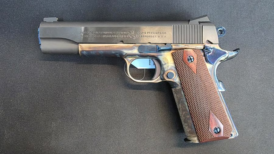
Now I am the first to admit that I am NOT a fan of the 1911’s. In that I could never get a consistent shot pattern. That & they are a pain in the ass to field strip. I won’t mention all the springs that I have lost over the years.
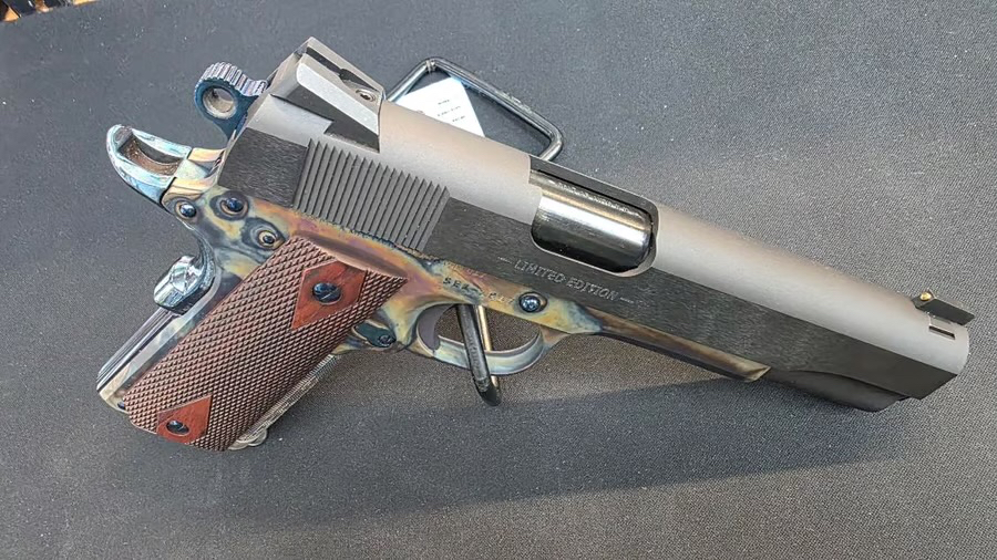
Now having said all that. Here is another grip of mine about this piece. Notice the checkering on the grip? We, yours truly got the “privilege” of shooting one.
Well after firing off 5 rounds. I had found that this checkering was like holding a course file. That took off any calluses I had on my hands and I was actually bleeding from shooting the beast.
So take this advice for what it’s worth.For myself, well I do so love my Sig P220! Grumpy
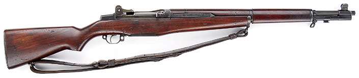
One of the most famous and respected U.S. military service rifles of all time is the “U.S. Rifle, Caliber .30, M1,” popularly known as the M1 Garand in recognition of its inventor, John C. Garand. The rifle is well-known due its widespread use in World War II and Korea, as well as its popularity with many present-day collectors and shooters.
What is not so widely known, however, is that the rifle as originally adopted in 1936 and manufactured for the first four years was markedly different in one aspect from the version so well-regarded today.
The genesis of the M1 began shortly after World War I in 1919, when John Garand was hired to work at Springfield Armory on the development of a semi-automatic rifle. Even before Garand was employed, a number of domestic and foreign semi-automatic rifle designs had been evaluated at Springfield, but none had proven to be satisfactory.
One of the more promising designs was the Danish Bang rifle, which featured a “muzzle cap” that trapped the escaping gas after it exited the muzzle and utilized it to operate the rifle’s action. First tested in 1911, several variations of the Bang rifle were evaluated at Springfield as late as 1928.
After some experimentation, including an unusual primer-actuated design, John Garand settled on a gas-operated mechanism for his rifle. Although the Bang rifle had not proven to be satisfactory overall, Garand undoubtedly was influenced to some degree by the rifle’s gas system.
His gas-operated T1 prototype rifle was chambered for the standard .30 Springfield (.30-’06 Sprg.) cartridge, but Garand was directed by Ordnance to scale down the rifle to a .276-cal. cartridge championed by John Pedersen, who also had a semi-automatic rifle in parallel development at Springfield Armory during that time.
Designated as the T3E2, Garand’s .276-cal. rifle subsequently edged out the Pedersen design and was recommended for adoption. Nonetheless, for several reasons, the War Dept. disapproved of the .276 cartridge and mandated the rifle instead be chambered for the .30-cal. cartridge, which had been John Garand’s preference all along.
In 1934, 80 such .30-cal. rifles, designated as the T1E2, were fabricated in Springfield Armory’s Model Shop and thoroughly tested with very good results at several Ordnance facilities.
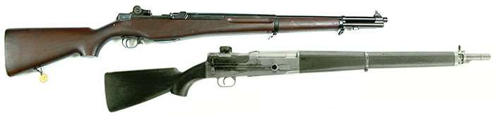
An experimental T3E2 Garand (top) is shown with a variation of the Danish Bang semi-automatic rifle (bottom) tested at Springfield Armory in late-1918.
The rifle was adopted on Jan. 9, 1936, as the “U.S. Rifle, Semiautomatic, Caliber .30 M1.” “Semiautomatic” was soon dropped from the nomenclature as there was no need to denote the type of mechanism.
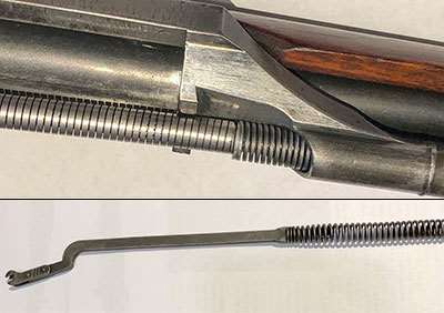
The follower rod on a gas trap M1 rifle is fitted with a “square wire” operating rod spring and separate compensating spring (above). Note how they differ from the follower rod and familiar “round wire” operating rod spring of a World War II-production M1 rifle, which is not accompanied by a compensating spring (below).
A signature feature of the new M1 was its Bang-influenced gas system, which has been dubbed by collectors today as the “gas trap” in recognition of the manner by which the escaping gas was collected.
The front sight on early-production rifles had straight protective ears, but it was found that inexperienced shooters sometimes mistook one of the ears for the sight blade—which was obviously deleterious to accuracy. The problem was soon corrected by making the ears flared so they were easily distinguishable from the front sight blade.
The rear sight was one of the best ever used on a military service rifle, before or since. It had a peep aperture and was easily adjustable for windage and elevation. The windage knob was secured to the pinion by a spanner nut.
A feature unique to the “gas trap” rifles was a metal “lip-type” ferrule that separated the front handguard from the gas cylinder. These rifles also utilized an operating rod spring and separate compensating spring that were of the keystone (square wire) configuration. As originally adopted, the M1’s stock did not have a recess in the butt for storage of cleaning implements, etc., and used a one-piece solid buttplate.
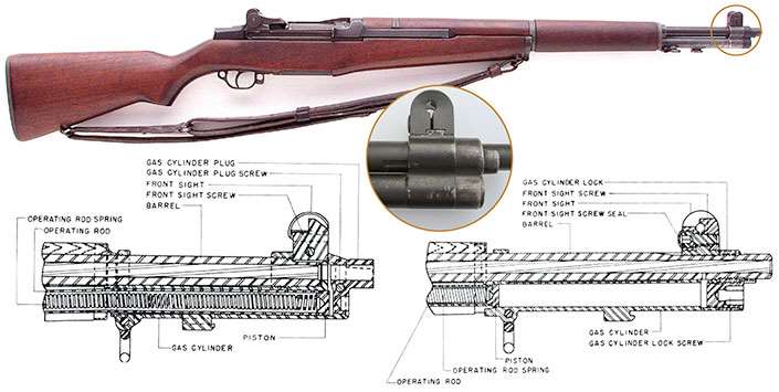
The muzzle of a “gas port” Garand (inset) will be familiar to most modern-day Garand owners. Ordnance Dept. drawings reveal internal views of the gas trap (below, l.) vs. gas port mechanisms.
When inspection of a rifle was successfully completed after manufacture, a Final Inspection Stamp, often colloquially termed a “cartouche” by collectors today, was impressed into the left side of the stock. The stamp consisted of “SA/SPG.” “SA” indicated manufacture by Springfield Armory and “SPG” represented the initials of Chief of Small Arms Inspection Stanley P. Gibbs, who was a civilian employee at Springfield. All of the “gas trap” M1 rifles bare Gibbs’ inspection stamp.
Another interesting feature of the gas trap M1s was the presence of “Drawing Numbers” on most components consisting of a letter prefix (“A” through “F”) that denoted the size of the component and a number that identified the specific part. As many of the parts were subsequently changed for better performance or easier manufacture, a “revision number” was added.
For example, the initial Drawing Number of the rear sight aperture was “B-8868,” and with the first revision of the component it was changed to “B-8868-1.” The Ordnance Dept. eventually came to the conclusion that the marking of so many parts wasn’t worth the effort, and, as production continued, fewer and fewer parts had Drawing Numbers applied.
Eventually, only the major components, such as the receiver, barrel, operating rod, bolt and trigger housing were marked with Drawing Numbers.
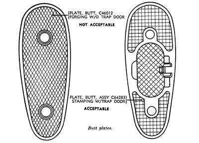
An Ordnance Dept. drawing shows the early, solid M1 rifle buttplate (l.) as found on gas trap rifles and very early gas port rifles. The later and more common buttplate has a hinged door to access the butt trap recess.
While many small nagging glitches cropped up and were solved one-by-one during the initial course of production, a major problem occurred when it was found that many of the new rifles jammed on the seventh shot.
Finding the cause of the so-called “seventh round stoppage” resulted in Springfield Armory engineers having to burn the midnight oil. It was eventually determined to be a slight deviation in John Garand’s original specifications. The tooling was changed, and most of the affected receivers were modified to rectify the problem, and the rifles remained in use.
The first M1 rifles saw very limited issuance in the fall of 1937 when a total of 48 rifles were sent to five different Army bases. Since only a small number of the rifles were starting to be issued, few soldiers had seen an example.
The new semi-automatic rifle was certainly a revelation to the relative handful of soldiers who had the opportunity to fire the Garand, and the vast majority of those preferred it to the bolt-action M1903 rifle.
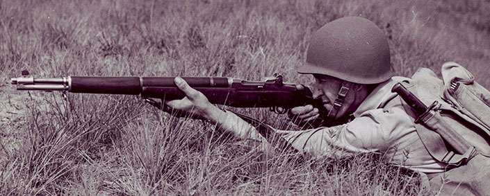
This World War II-era photo shows a U.S. Army infantryman firing a gas trap M1 rifle. A surprising number of unaltered gas trap rifles saw active use during the war.
Many soldiers who had never been anywhere near an M1 bad-mouthed the rifle due to a lot of unfounded rumors floating around the barracks. Much of this angst was due to the simple fact that many people are reluctant to accept change, and the M1 rifle certainly represented change.
As the rifles began to see more field use, however, another problem surfaced. The “gas trap” gas cylinder proved to have several weaknesses. The screw that held the gas cylinder plug in place could become loose, thus causing the gas cylinder to become slightly misaligned. This could result in a bullet striking part of the gas cylinder and blowing it off the end of the barrel.
This wasn’t terribly common, but it did occasionally happen—and it needed to be fixed. Also, extensive firing could result in carbon build-up inside the gas cylinder. It was hard to get cleaning patches into the gas cylinder, and it was often necessary to disassemble the component in order to clean it properly. It has been said that it sometimes took a chisel to get out the accumulated carbon. Also, the gas cylinder was not a particularly strong attachment point for the bayonet.
John Garand, working in conjunction with the Springfield Armory Engineering Dept., developed a new gas system that was ready for preliminary testing in early 1939. Rather than trapping the gas after it left the muzzle, Garand’s new design had a port drilled into the bottom of the barrel through which the gas was channeled to impinge on the operating rod.
Interestingly, Ordnance Dept. and Springfield Armory documents of the period routinely referred to the gas systems as the old and new “front ends,” decidedly untechnical terms. A letter dated March 8, 1939, from Ordnance Maj. Guy H. Drewry to Lt. Col. Raymond Marsh at Fort Benning stated:
”The new front end has gone through a 10,000 round test and it has been found necessary to make some minor changes. These are primarily, however, to facilitate production. The functioning during the test was very good. We are planning to equip ten rifles with the new front end and send them to Benning for test and observation just as soon as we can. This will probably be some time within the next two or three months.”
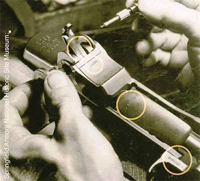
A worker assembles an early gas trap M1 rifle at Springfield Armory. Note the Drawing Numbers on the rear sight aperture, rear sight cover, bolt and operating rod.
The refinements on the new gas system apparently took a bit longer than originally anticipated, and Maj. Drewry followed up with a letter to Capt. H.G. Sydenham at Fort Benning on June 10, 1939:
“The new front end for the M1 Rifle is coming along fine. We expect to send down shortly to Benning eight or ten rifles with the new front end for test. The main trouble that we have had has been in determining the proper size of the gas port for the most efficient operation.”
This letter was followed by one written Oct. 4, 1939, from Maj. Drewry to Col. Marsh: “The ten U.S. Rifles, Caliber .30, M1, with the new front end were shipped from Springfield Armory on September 27, 1939, by express, so I imagine they have probably arrived there by this time and are being tested. I hope these tests can be completed as early as practicable so that we may obtain clearance for this design.”
Testing at Fort Benning (and elsewhere) did indeed validate the new gas system, and the design was recommended for adoption by the Ordnance Committee on Oct. 26, 1939. The Springfield Armory Annual Report for Fiscal Year 1939 contained the following details regarding the new gas system for the M1 rifle under the heading “The following developments in technological processes and engineering practices have been developed by the department during the past year:
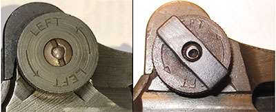
The rear sight windage knob with spanner nut used on gas trap and gas port rifles manufactured prior to circa 1942 (l.) was somewhat lower-profile than that of World War II-vintage rear sight windage knobs, which used a “locking bar” that could be hand-tightened to hold adjustments more securely.
[N]ew method of securing Gas Cylinder Assembly to the Barrel of the M1 Rifle and an improved method of trapping gases required for operation. The newly developed gas cylinder assembly not only provides a more rigid and positive positioning of the gas cylinder on the barrel but eliminates variations in the size of the gas orifice and greatly improves the accuracy of the piece. Ease of maintenance has been of paramount consideration during the design of the assembly and the cost to produce it will be less than that of the previous model.
In addition to the rifles sent to Aberdeen, a number of others were distributed to Frankford Arsenal, the Cavalry Board and the Infantry Board. The Springfield Armory Annual Report for Fiscal Year 1940 (July 1, 1939 to June 30, 1940) stated the following regarding the new gas cylinder:
Delivery of the re-designed front end for the M1 rifle started in June, 1940. At the present the machinery for the old front end is rapidly being adapted to the manufacture of the new components in greater quantities.
Even though the new “gas port” barrel was 24″ in length as compared to the 22″ barrel of the “gas trap” model, the overall length of the revised rifle remained about the same since the “false muzzle” of the original design was eliminated. The rifle’s weight of approximately 9 lbs., 8 ozs., was not affected by the change in gas systems.
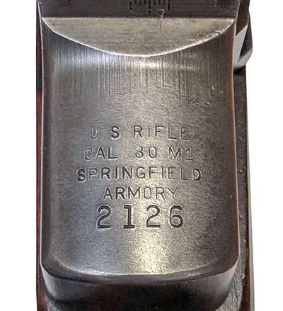
M1 rifle Serial No. 2126, manufactured at Springfield Armory in April of 1938, still remains in its original “gas trap” configuration.
Even after the order was given to change over to the new design, M1 rifles with the older gas system continued in production so that the existing supply of earlier parts could be used up. Thus, it was not until August 1940 that the last of the gas trap M1s came off Springfield Armory’s assembly line.
By this time, some 32,000 additional rifles of this pattern had been manufactured. It should be noted that this figure represents the number of gas trap M1s made after the new gas system had been adopted but before the tooling was changed to incorporate it into the manufacturing process.
A memorandum from the Subcommittee on Small Arms to the Ordnance Technical Committee contained the following information pertaining to the adoption of the new gas system. The memo makes it clear that the gas trap rifles already issued were to remain in service until substantial repair, such as barrel replacement, was required. The memo also disclosed the number of rifles that had been manufactured with the older gas system:
Reference a. covers the adoption of a new gas cylinder for the M1 Rifle. It recommends the adoption of the new design of gas cylinder for current manufacture. However, no mention is made concerning the disposition of rifles having the old style gas cylinders after the barrels thereof become unserviceable and require replacing. There were approximately 48,119 of the subject rifles manufactured with the old style gas cylinders and barrels.
Recommendations
This sub-committee recommends that the authorization be granted to replace the old style gas cylinders and barrels with the new style gas cylinders and barrels, as the old assemblies become unserviceable.
While this document reveals the number of gas trap rifles originally made, there are still some questions regarding the serial number range for these rifles. For example, it is known that some gas port rifles assembled in mid-1941 were in the 40,000 serial number range, and serial numbers as high as the 51,500 range have been reported by credible sources as original gas trap rifles.
This overlap in serial numbers between gas trap and gas port M1 rifles during this period was a case of the Ordnance Dept. using up gas trap parts still on hand in order to put as many M1 rifles into the hands of troops as possible, even if they weren’t of the latest design.
A surprising number of unaltered gas trap rifles saw service during World War II and were not updated to gas port configuration until sent to ordnance facilities to be rebuilt during, and after, the war.
After 1940, gas port M1 rifles that passed inspection at Springfield were stamped “SA” along with the initials of the Armory’s Commanding Officer. Unlike the “SA/SPG”-marked gas trap M1 rifles, the Final Inspection Stamps of the commanding officers of Springfield were also accompanied by the now familiar Ordnance Dept. “crossed cannons” escutcheon.
While the new gas cylinder was the most notable change in the design of the M1 rifle, numerous other modifications were made during the course of production.
These included elimination of the separate compensating spring, a change from a keystone spring to the more familiar “round-wire” spring and the incorporation of a buttstock recess that was accessed by a buttplate having a hinged trapdoor. It was found that the rear sight did not always hold the adjustments securely, and early in World War II the spanner nut on the windage knob was replaced by a “locking bar” that could be hand-tightened.
As the gas trap rifles were subsequently rebuilt and converted to gas port configuration, they were fitted with the updated parts. Typically, all that remained from a gas trap rifle after rebuild was the receiver, and even that part was modified to correct the “Seventh Round Stoppage” defect.
Despite the myriad changes made in the various components of the M1 rifle as production continued through 1957, the revised gas system was the only major modification of the rifle since its adoption in 1936.
It should be noted that even if the gas system had not been changed, John Garand’s rifle would still have been the best general-issue semi-automatic service rifle fielded in significant quantity by any nation during World War II. The change from the gas trap to the gas port system simply made a good rifle even better.
Today, the M1 rifle enjoys tremendous popularity with many collectors and shooters. For a collector, the acquisition of an original gas trap Garand is a worthwhile, but extremely elusive, goal. It is widely considered the “Holy Grail” of M1 collectibles, as well as a little-known, yet historically significant, U.S. military rifle.
Greetings Me Droogs N Droogettes!
Thank goodness for .xml files. I was able to pull the Flammenwerfer original poasts and save them to Word Documents, which I’m reproducing here.
Now, with the understanding that prices have gone pretty much insane since 2019 when I did the original project, expect MOAR Fiatbux to be spent on the whole kit and kaboodle.
Also, this’s the Mark One, Mod Zero Flammenwerfer.
There have been Modifications that’ve been done to improve the build and ease of things. I’ll include details on that after the fact. But, Poast One, Page One:
DISCLAIMER THIS IS STRICTLY FOR LAUGHS AND EDUCATIONAL PURPOSES ONLY. REAL SMART PEOPLE –DO NOT– BUILD HOME MADE FLAME THROWERS.
PROCEED AT YOUR OWN RISK, THE WEBMASTER AND THE CHAIRMAN DISAVAOW ANYTHING STUPID YOU MAY DO.
DO NOT RUN WITH SCISSOR, NOR TAUNT HAPPY FUN BALL
YMMV
“In the United States, private ownership of flamethrower is not restricted by federal law. Flamethrowers are legal in 48 states and restricted in California and Maryland.”
Yep. Legal. Suck it Fuzzballs.
It dawned on me just -why- they’re so terrified.
(insert music and deep voice) Since the Dawn of Time, fewer things have terrified man, and proto-man more than burning to death. (end music) Horrible way to go really. And here the fuzz were in a stand off with an at the time mentally unbalanced dude with the ability to roast them alive. As you can see, the ‘throw’ on it was about 40-50 feet, but thats because I was running pure 87 octane which burned off w/out sticking… if I had been running Napalm, the throw goes out to 80-100 feet…
In CQB thats good enough to count along with Horseshoes, Hand Grenades, Nukes, and Bad Analogies.
Kevlar doesn’t do shit. In fact, Kevlar is a ‘no-no’ as it melts and adheres to the skin. If I had decided (not that I could) to go Full Retard, the night might have made international news, never mind national or local. Thankfully it didn’t happen.
But in the interest of these now Screaming Socialists and Retardigans running for the Orifice of the Criminal In Chief, I thought it was my public duty to inform my readership as to the alternatives to an AR-15. Home defense has never been so much fun, but be aware it’s as dangerous to the user, and I -highly- recommend that the novice NOT fuck around.
LEGAL DISCLAIMER: Do NOT try this at Home. Do NOT build a flame thrower if you are a fucking moron with delusions of being a handyman. Do not use to dry pets. The author is strictly relaying humorous and theoretical anecdotes so please don’t blame me if you F.A.F.O. DO NOT BUILD IF IN THE STATE OF MARYLAND OR CALIFORNIA. Them fuckers got no sense of humor.
That being said and out of the way? as I said.
Legal.
Scares the FUCK out of Coparoaches.
Did I mention easy as fuck to build if yer not a complete fucking idiot?
And cheap? I got ALL the parts on Amazon with Prime shipping for less than $350. (This now being Modified by X2)
Red Flag Laws you say? Flammenwerfer I say. F.A.F.O. Mister “I’m here to arrest you because you didn’t follow the law!”
Thats rich.
Confiscation?
Bring it.
Now, onto Page Two:
These are all the pieces-parts I used to make the Flammenwerfer Mark One Mod Zero. The Link will take you to the part (if they aren’t dead) and Yes, I do get a taste of the vig as it took quite a while to put this all together.
Said Parts List:
20 lb CO2 Tank https://amzn.to/2muHXH0
Now a note on the tank. You can get a 10 pound Tank Like I made for one of the readers here. He wanted lighter, and was willing to sacrifice burn time/ammo for maneuverability. Also, a 15 or 10 pound tank costs less. Jes’ Sayin’
Cambuckle Cargo Straps, no hooks (for securing the tank to the frame) https://amzn.to/2mXZlV3
I -think- that rounds up the pieces parts.
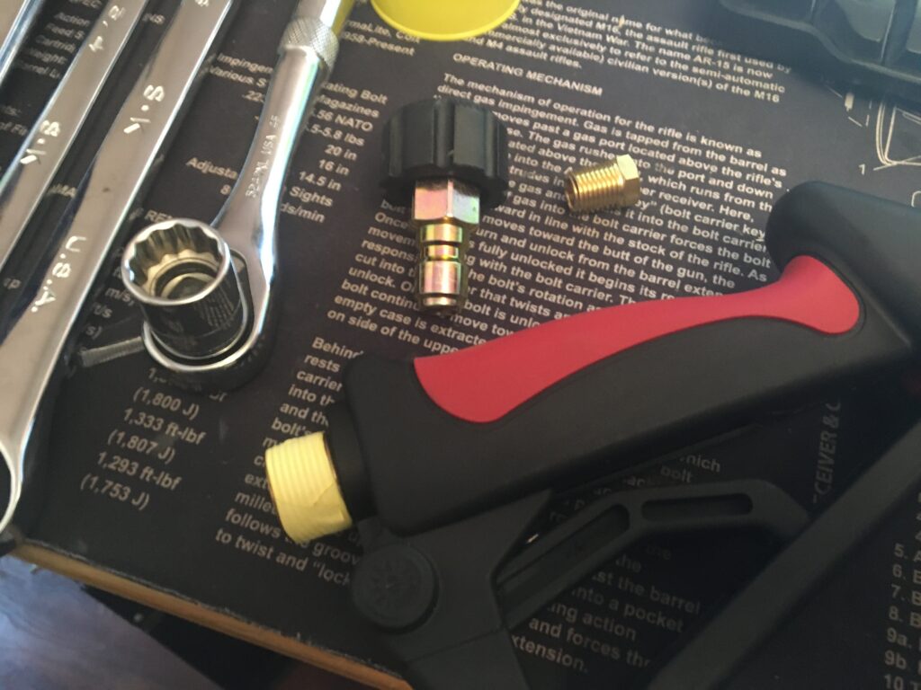
Next is the Tools.
The list with the links attached are NOT the common stuff a dood or doodette might have laying about in “Ye Olde Toolboxe” So I linked them for convenience. The stuff w/out links -should- be in yer basic home/car repair kit, and if not, then shame on you.
The Rest Y’all should have if you’ve got a basic toolbox.
1” Wrench
7/8” wrench
¾” Wrench
½” Drive socket Wrench
3/8” Drive socket Wrench
3/8” Drive 8” Extension Bar
11/16” Deep Socket ½” Drive
15mm Deep Socket 3/8” Drive
9/16” 8-Point Socket ½” Drive
5/8” Socket ½” Drive
½” Socket 3/8” Drive
Pliers, Needle Nose
Center Punch
2mm Allen Wrench
Cutting Oil
Flathead Screwdriver
Damn… Lot of ‘stuff’…
No wonder I’ve been a lazy bastard and keep putting this off.
ASSEMBLY TIME
For the sake of clarity, Parts will be in BOLD BLACK
Tools will be shown in BOLD ITALIC
So Step One:
I started off by doing accountability of ALL the parts. Once I had them together, I literally started from the top down. First thing, Take the Main tank, the 20LB Large Tank, and using the 1 ¼ INCH WRENCH remove the Tank Fill Valve. Depending on which model you bought, there may be a spinning black plastic guard. This does NOT need to be removed. In fact, I suggest leaving it on there to assist in protecting the Tank Fill Valve.
Step Two:
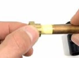
Using the Yellow Teflon Tape, wrap the threads of the Tank Fill Valve on the upper part of the valve. DO NOT WRAP THE BASE OF THE VALVE. This’s because it’ll make it impossible to remove it from the tank when you are trying to refill the Main Tank.
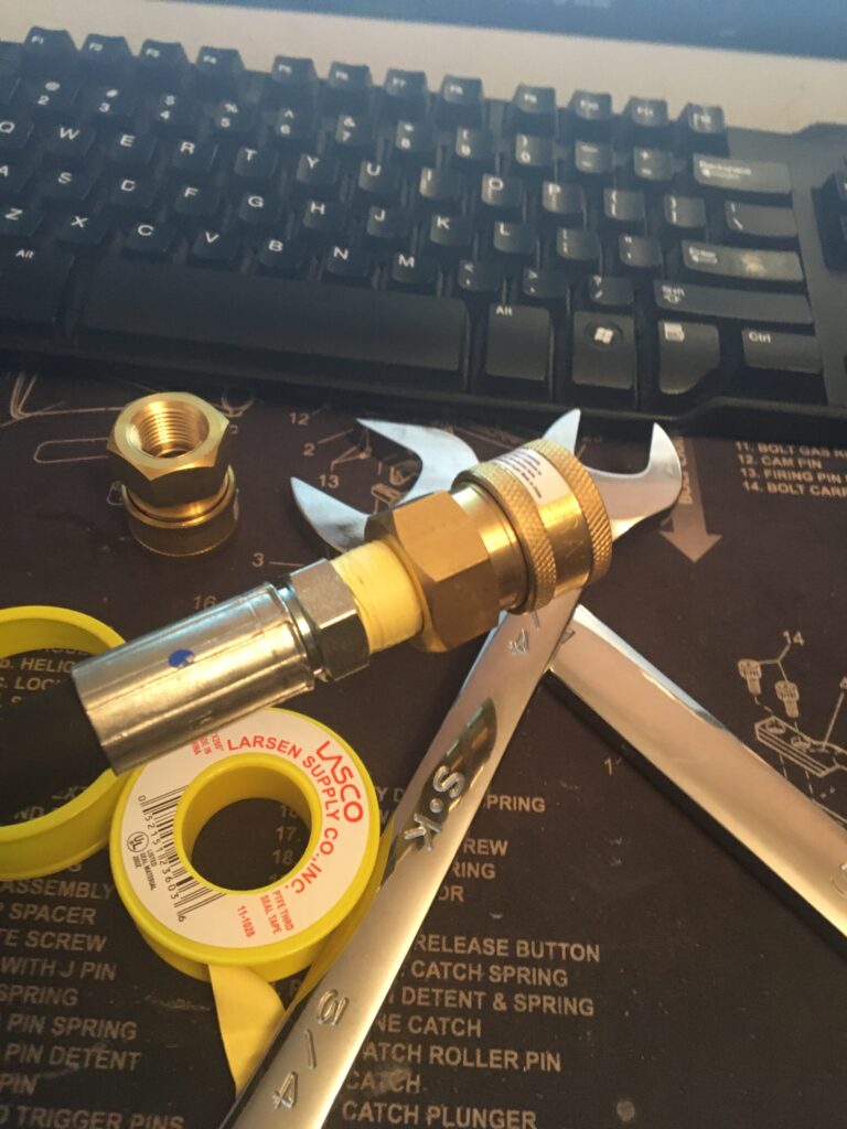
And do the same. Wrap all of the threaded sections of the gathered parts with between 2 ½ to 3 turns on the threads. Make sure its neat and tight and that you cut it away -cleanly-. Put these aside for now, but have them ready for:
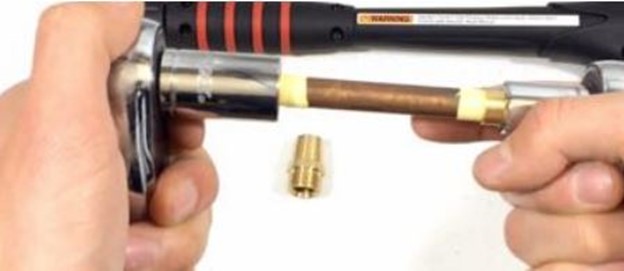
Take the small brass nut from the 320 cga female to 1/8″ female NPT and thread it onto the 1/8” male NPT to 1/8” male NPT x 4.5” length Tighten as much as you can by hand.
Take this assembly, and insert the tube into the Large Brass Nut like so:
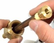
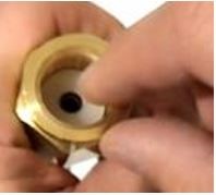
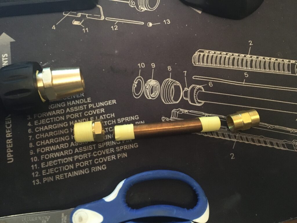
Once you have this ready, the Large Brass Nut should be hanging relatively loose. Get The Universal Paint Ball Fill Adapter, and insert the other end of the 1/8” male NPT to 1/8” male NPT x 4.5” length
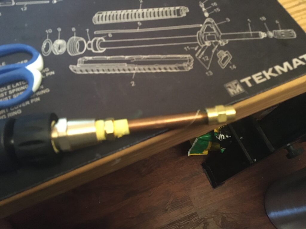
Into the 1/8th hole in the side of the Fill Adapter. Once its hand tight, get the11/16” Deep Socket ½” Driveand the 1/2inch drive socket. Slide the Large Brass Nut off of the Small Brass Nut and insert the Small Brass Nut into the 11/16” Deep Socket ½” Drive and -FIRMLY- crank the 1/8” male all the way into the Paint Ball Fill Adapter. Make sure its nice n’ tight, as this is a potential leak area where the propellant gasses are going to be feeding the Flammenwerfer. Once its good, slide the small nutback into the Large nut, insert the Plastic White Washer into the Large Bass Nut to secure the small nut inside. Click it in place so the tube is locked in place.
Once this’s completed, you should have an assembly that looks like this:
The next step is a Pressure test. I suggest doing this first so that you know you ain’t got no leaks. Especially before you start drilling on the tank itself, because once that’s done, chasing itty-bitty air leaks is a stone bitch (as I found out the hard way.)
Step Four: Air Pressure Assembly Test
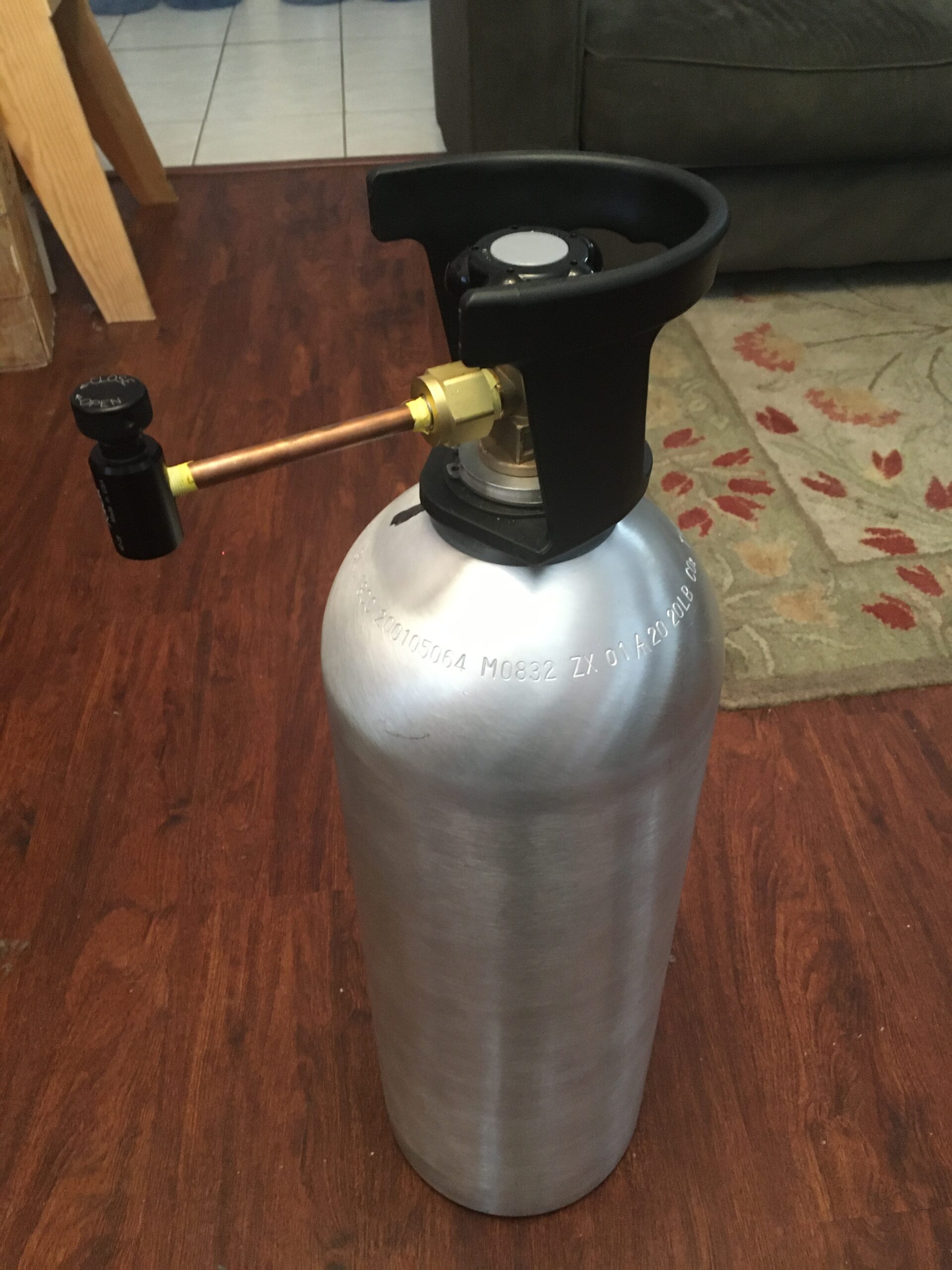
Reassemble the Tank Fill Valve onto the tank. Be careful re-threading it on the tank. The tank is aluminum, and if you cross thread it, say goodbye to about $100. Once you have it on, (being careful of the plastic guard, give the Fill Valve a slightly more-than-hand-tight spin. You -don’t- want to crank down on it. Just enough for the rubber gasket to fully engage.
What You DO need to get ready is the1-1/8” wrench. You’ll be utilizing this on the Large Brass Nut to crank the assembly nice n’tight. The Universal Filler Valve needs to be vertical with it’s valve on top.
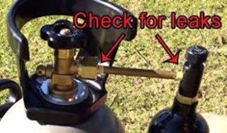
And take it down to the local paintball store to get it filled. Should be about 5 bux to get it filled. This’s why I like to have a few extra (2X for a total of 3) on hand. Once it’s filled, bring it home and get s dish with some soapy water for a leak test. 2:1 ratio dawn detergent so it’ll blow nice bubbles if/when it leaks. Install it into the Universal Filler Valve. Make sure that you have both valve(s)closed BEFORE you install the CO2 tank.
Insert the CO2 tank into the Universal Filler Valve first. Look and listen to see if it is holding pressure. If so, Open the Valve. Watch the seams on the junction points. Dribble some soapy water on it. Observe. No bubbles = good. Open the Main Tank Valve. You should hear the tank fill with CO2 and become pressurized. Be VERY CAREFUL while doing this. I recommend Eye Protection and leather gloves in case -something- ruptures.
If there are no apparent leaks, Turn off the Valves in reverse order. Remove the CO2 Tank SLOWLY. Bleed off the CO2 CAREFULLY EVERY STEP OF THE WAY. Fuck around, and you’ll find out the hard way.
Now, We’re gonna tackle the main Tank Prep, as in Prepping, drilling and tapping, then installing the bayonet valve that the hose will be attached to. For this evolution, You’ll need the following part:
Drill press with 1/2” chuck -or- (b) Power drill with 1/2″ chuck
1/2” drive socket wrench
9/16” 8-point socket 1/2” drive
1/2” Dewalt pilot-point drill bit
37/64” Drill bit
3/8″-18 NPT thread tap
Cutting oil
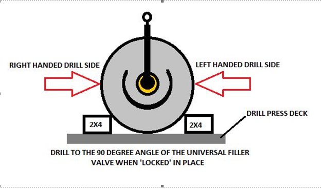
Setup is as Follows. At this point you’ve reattached the newly built Universal Filler Valve and tightened it down when performing your pressure/overpressure test. With it set in the drill press (or workbench) measure out 90 degrees on either the left side or right side.
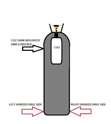
Because the hose that feeds the fuel to the nozzle is only 3-4 foot long (I used a 3 foot hose) you need to insure that you cut in on the correct side of the tank. If yer a righty, cut on the right side. If’n yer a southpaw, cut left. Once you unfuck yerself on the whole left/right thing, just realize that the pressure container, the 24oz CO2 Tankhttps://amzn.to/2moGdzl is going to be centered on the back of the tank on your frame.
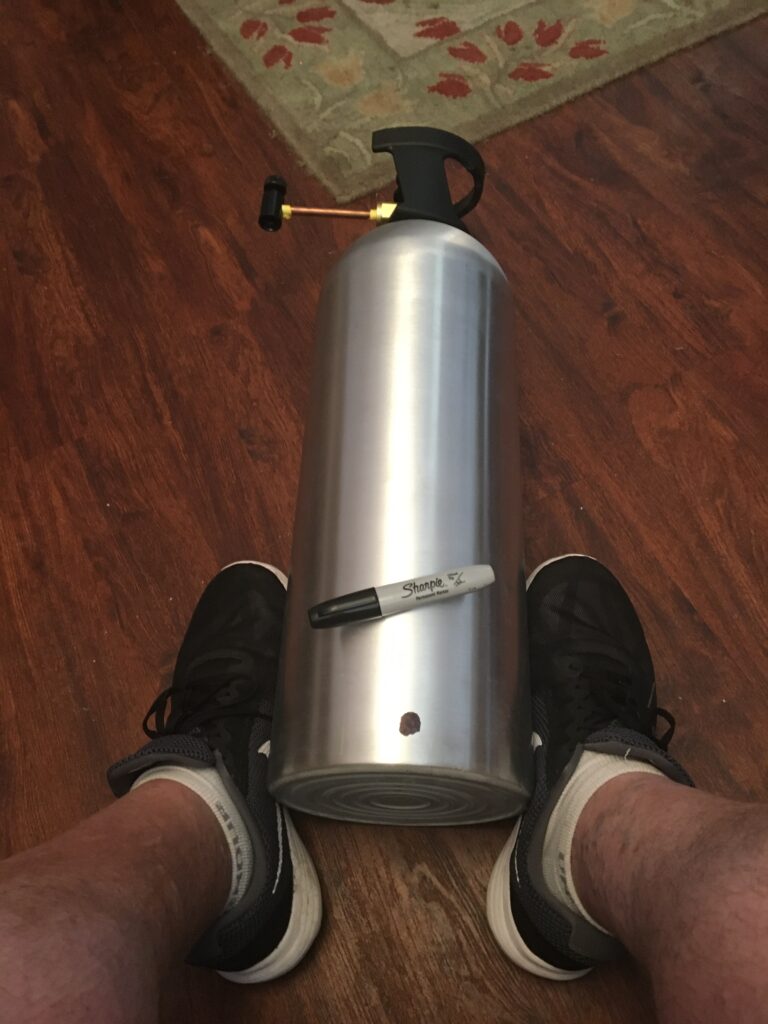
Once you have the side picked out, Remove the Universal Tank Filler / Pressurization System. Mark the side you want to use roughly one inch from the bottom. Once you have the tank stripped down, roll it 90 degrees up to the side you wish to drill. Measure ONE INCH from the base of the 20 lb CO2 Tank and https://amzn.to/2muHXH0 and then prep to drill.
Make sure the tank is secure. Squirt a lil cuttin’ oil on the spot your going to drill. Using the 1/2” Dewalt pilot-point drill bit, begin cutting into the tank -SLOWLY AND CAREFULLY-. You’ll be getting a huge amount of shavings and keep adding the cutting oil as needed. Take your time and do it in stages is my approach.
This is your starting hole. Once it’s cleanly punched through, change out to the larger finishing bit, the 37/64” Drill bit. Add more cutting oil, and cleanly cut out the remaining metal, expanding the hole to 37/64ths.
OK. So now you got the hole. Take the square side of the 3/8″-18 NPT thread tap into the 9/16” 8-point socket 1/2” drive and insert the threaded side of the 3/8″-18 NPT thread tap into the 37/64” hole. Begin cutting the threads by turning the 3/8″-18 NPT thread tap clockwise ensuring that the 3/8″-18 NPT thread tap is perpendicular to the surface of the large tank.
There is NO SUCH THING AS BEING TOO CAREFUL OR SLOW! Make sure you cut slowly, adding cutting oil regularly so’s the thread cutter doesn’t get bonded or stuck to the metal. Continue cutting until only 6-7 threads of the 3/8″-18 NPT thread tap are exposed above the surface of the large tank. This -should- complete this evolution.
Step Two: Rinse out the tank.
Now that you’ve drilled and tapped the tank, you HAVE to make sure you get ALL of the little fiddly bits of shavings and metal out of the tank. Very carefully so as to not to damage the threads, use an old toothbrush or gun cleaning toothbrush to remove any clinging bits of aluminum around the tap hole. Blow out / shake out all remaining bit. Me? I triple rinsed with water, shaking the shit out of the tank to make sure it was clean. One itty-bit of metal in there when yer doing ‘flame on’ can cause BIG “Fiery-Ball-O’Death” Issues. Big Safety Tip: Thoroughly clean the tank.
Take the Male Quick Disconnect x 3/8” Male NPT and wrap two to 2.5 times around the threads. Mate up the threads to the 37/64” hole and thread it in. Once you have it cleanly started, finish securing it completely to the tank using the socket wrench and 11/16 drive.
Annnnnnd more to go… we’re almost completed on the hard stuff… the rest is pretty easy. Lotsa pressure checks and a bit more modifications to the pressure washer wand, but for the most part, some of y’all cool kids make be able to figure out the rest….
and one last time for the slow kids in the back:
DISCLAIMER:
I AIN’T RESPONSIBLE FOR SHIT.
I KNOW NUTHIN’ I HEAR NUTHIN’ AND I SEE NUTHIN’.
THIS’S STRICTLY FOR ENTERTAINMENT PURPOSES
AND IF YOU ARE CRAZY ENOUGH
TO FOLLOW THE BOUNCING BALL, ITS -ALL- ON YOU.
Now: Part 4 of this is going to be the Hose and Gun Build.
Simple really. Wrap all the parts with the Yellow Teflon Tape. It’s really important to use the yellow as it’s resistant to petroleum based stuff like, oh Napalm and gas… using -regular- Teflon tape and yer hosed (pardon the pun.)
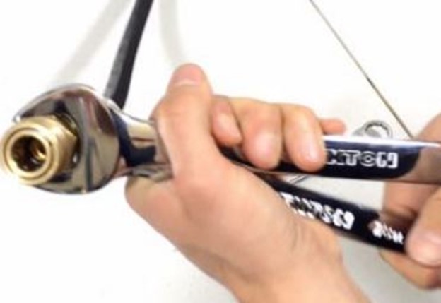
You’ll want to connect the hose(s) to the fittings hand tight at first, then crank them down with the wrenches thusly:
Scissoring them nice n’ tight. You do NOT want any leaks in the hose area. Things could get HOT muy malo.
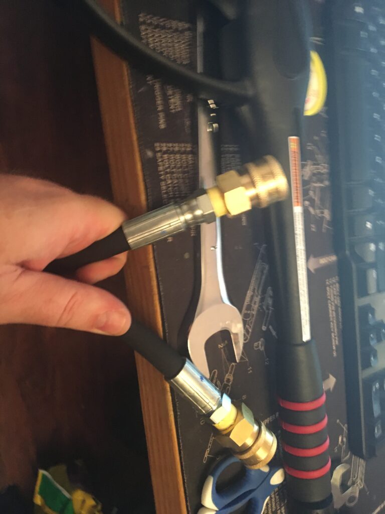
OK… once thats done, you can connect the hose to your previously built tank and see if it fits. The quick releases are the bomb so to speak b/c it allows you to clear each section IF and only IF you have a clog or something goes pear-shaped during the running of this.
16.4 oz Propane Cylinder (I buy mine at Lowes or Home Depot)
Tools Needed:
½” Drive socket Wrench
3/8” Drive socket Wrench
5/8” Socket ½” Drive
½” Socket 3/8” Drive
7/8 Wrench
OK Starting with the Red Brass Seamless Pipe Fitting, Nipple, Schedule 80, 1/8″ NPT Male X 3″ Length https://amzn.to/2kSl6VD, Tape all the threads again: (Small hint: do this to ALL THE THREADED PIECES PARTS. It’s a given that like -everything- on this puppy needs to be neatly sealed.) Once it’s ready, take the 2X Anderson Metals Brass Pipe Fitting, Coupling, 1/8″ x 1/8″ Female Pipe https://amzn.to/2lrNJsPand mount them on the pipe you just wrapped (heh… that sounds obscene…) Use the two socket drives thusly to insure again a -tight- fit:
Then take the M22 Male x 1/4” Female NPT https://amzn.to/2mpaEp2and crank THAT on. Once you have that installed, attach it to the front of the sprayer. You now have the gun completed ALMOST. The only thing left is to attach the Erie Tools Pressure Washer Twist Connect M22 X 3/8″ Quick Disconnect Plug 4500PSI High Pressure Brass Fitting 300° F Max Temp https://amzn.to/2lpJq1j to the end of the feed assembly.
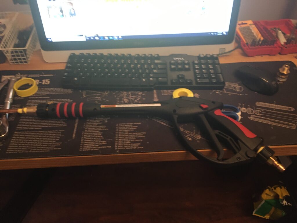
Once this is done, you should be able to do a pressure test once you’ve connected the hoses to the tank and gun respectively. Give it a shot so to speak.
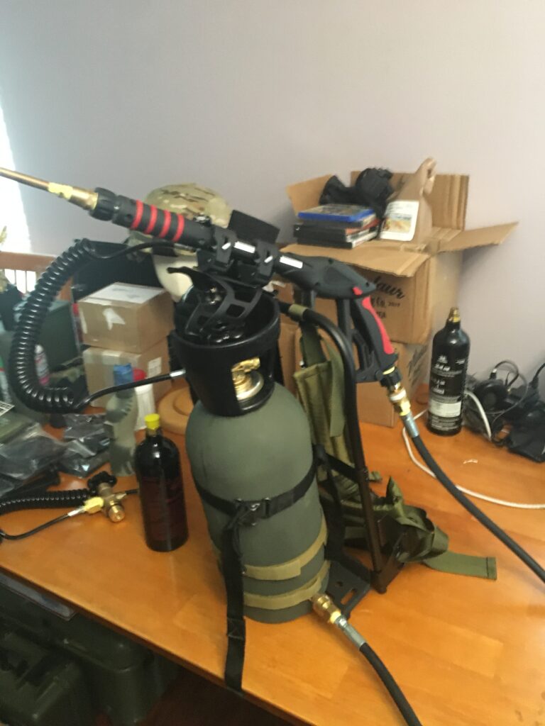
And it should look roughly like this:
Which then needs to have the propane tank slung underneath. For this I used some shims to stabilize it, and used the aforementioned Hose Clamps to strap it on. Adjustments will vary person-to-person. For that matter, it’s pretty much at this point complete.
Whew…
So there you have it.
“How to build your own Flammenwerfer”
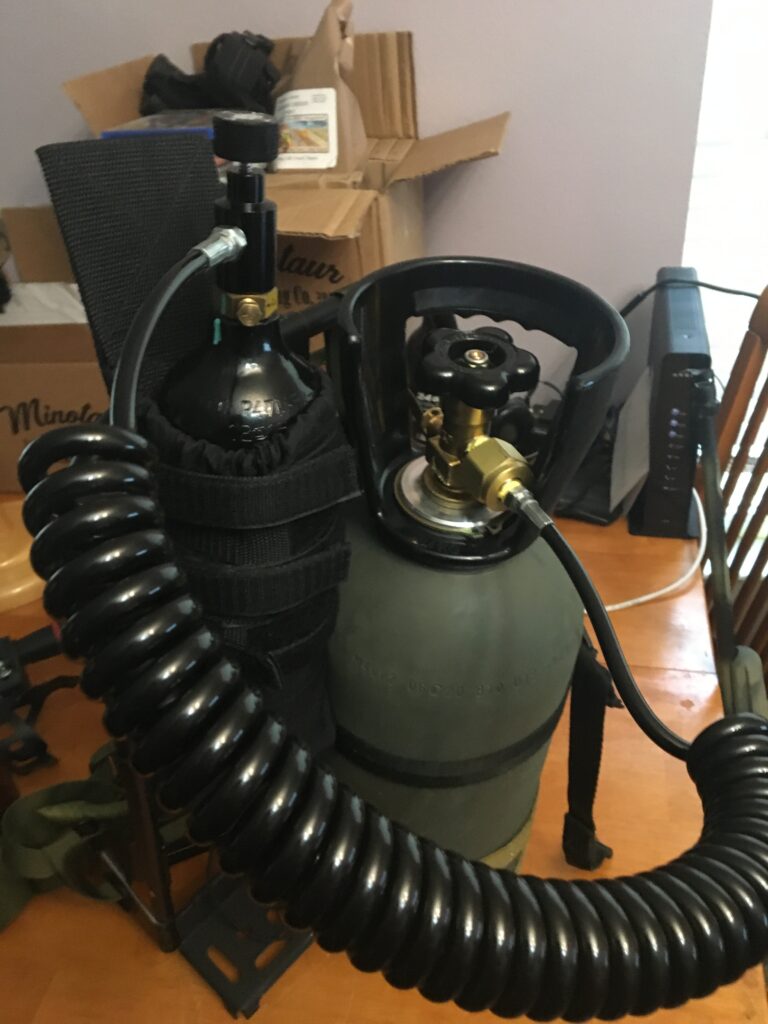
That right there is the mini I made for a customer. I also modified the air feeder from the brass to a 10 foot coiled hose (you see above) which alleviated the stiffness of the brass and the C02 tank ‘hanging’ off the feed. Too much tension IMO, so with the coiled hose, I was able to put the C02 bottle into a pouch, and hang it on the frame:
Transcript of an actual conversation I overheard among some Army buddies whilst waiting in an airport to fly off to someplace horrible many years ago:
“‘Batman versus the Terminator.”
“With or without his utility belt?”
“With, of course. Don’t be an idiot. Without his utility belt, Batman is just a dude.”
Three hours later, all the nearby women had wandered off to commit ritual seppuku. The men were still going strong, debating the finer points of batarangs against the Terminator’s armored endoskeleton.
Any place two or more guys are gathered there will invariably result spirited discourse about such weighty issues as superheroes and cinematic monsters. Where there is little disagreement, however, is regarding the greatest gun movie of all time. This film is, obviously, Michael Mann’s 1995 ballistic opus
“Heat.”
Origins of a Masterpiece
It’s hard to believe that “Heat” is 30 years old this year. Michael Mann, the directorial wunderkind behind this amazing film, is a freaking beast of a movie maker. His filmography spans a dozen theatrical movies, 14 TV series, and four made-for-TV features.
Among those 12 big budget films you will find such seminal epics as “The Keep,” “The Last of the Mohicans,” “Collateral,” “Miami Vice,” and “Public Enemies.” Though these films span many eras and genres, the common denominator is some simply amazing gun work.
Incidentally, “The Keep” was his second directorial effort, and it was amazing. Check it out if you haven’t already. You’ll thank me later. “Heat,” however, eclipsed them all.
“Heat” had a gripping story, a killer score, and the best acting talent in the industry. Al Pacino stars as Los Angeles police Lieutenant Vincent Hanna. Robert DeNiro is his opposite number, the leader of a murderous armed robbery crew named Neil McCauley. Val Kilmer, Jon Voight, Tom Sizemore, Wes Studi, Ashley Judd, Natalie Portman, Danny Trejo and others add some proper depth.
Curiously, one of the reasons Mann did such a bang-up job on “Heat” is that it wasn’t his first time to tell the story. The script for “Heat” began as a 1989 TV pilot called “LA Takedown.” “LA Takedown” used many of the same characters along with an abbreviated version of the narrative that Mann later utilized for “Heat.” Mann filmed this project in a mere 19 days. The movie ran on TV in August of 1989 and was intended to become a series before being canceled.
Both films were based upon an actual incident that occurred back in 1964. The real-life thief was really named Neil McCauley, an ex-Alcatraz inmate who began plotting fresh crimes as soon as he got out of prison. Unbeknownst to McCauley, an LA detective named Chuck Adamson was following at a distance.
McCauley and his crew robbed an armored car as it made a drop at the National Tea grocery store. While inside the store, the cops closed off the escape routes and a massive shootout ensued. McCauley was gunned down by the cops in the front yard of a nearby home.
Handgun types used in “Heat.”
Val Kilmer used a Beretta 84F in .380 ACP.
LAPD officers carried Beretta 92FS (left), while SWAT used customized 1911s (right).
DeNiro’s character used an HK USP (right) and SIG P220.
Cinematic Firepower
What really made “Heat” was the guns. There were dozens of different firearms used in the movie. We will just cover the high points.
DeNiro’s McCauley character begins the film with an HK USP before switching to a SIG P220. Pacino’s Hanna packs a Colt M1991A1 Series 80 Officer’s ACP in a cross-draw holster. Pacino press checks his 1911 prior to confronting one of the bad guys, which is a cool touch.
Val Kilmer’s character is shown with a Beretta 84FS. The LAPD officers pack standard Beretta 92FS pistols, which should be period correct. LAPD SWAT carry 1911’s, which is also spot-on.
SWAT officers are carrying what appear to be HK MP5A3 submachine guns. However, the astute gun nerd will note that they are actually converted HK94 9mm rifles. You can tell by the absence of tri-lug suppressor mounts on the barrels and the lack of flapper magazine releases. Normal people don’t care, but guys like me certainly do.
Factory-correct HK MP5 clones are both reasonably-priced and ubiquitous nowadays. However, back in the 1990’s, converting a real-deal German HK94 was the only way to get into an MP5 analog. These same guns were used in lots of movies made during this time period, “Die Hard” standing out among them.
Tom Sizemore’s character wields an FN FAL battle rifle in the opening armored car scene. When terminating a captive security guard he employs the classic Mozambique Drill of two to the chest and one to the head. We see the same thing on glorious display by Tom Cruise in the subsequent Michael Mann film “Collateral.”
Val Kilmer’s character uses an HK91 rifle without an optic from an overwatch position during the shootout at the abandoned drive-in. In his skilled hands, this full-power .308 battle rifle is appropriately effective against targets inside a pickup truck. He fires the weapon off of its folding bipod to excellent effect.
Mossberg shotguns of the type seen in “Heat.”
An Ithaca Stakeout made a cameo in “Heat.”
A Blaze of Glory
Everything in the movie leads up to the climactic scene wherein the cops surprise the crew coming out of the bank at the end. The robbers burst into the crowded lobby with their weapons and spare magazines under long coats, seizing the cash and exiting the building without any ancillary drama. Once outside, however, everything goes predictably sideways.
DeNiro and Kilmer are packing full-auto Colt Model 733 carbines. These stubby 5.56mm assault rifles sport 11.5-inch barrels and round handguards, this being the era before ubiquitous rails. Curiously, the M16A1 upper receivers sport A1 rear sights but include the A2-style brass deflectors.
Tom Sizemore wields a Galil ARM in 5.56mm. Wes Studi’s cop character carries an M16A1 outfitted with M16A2-style round handguards. The rest of the street cops carry a variety of shotguns.
Pacino’s character comes packing a short-barreled FN FNC carbine. The gun used in the film was selective fire and cut down from a long-barreled original.
However, Mann had Pacino use the gun in semi-auto-only as he was portraying a police officer. It was rightfully assumed that a cop would not be spraying rounds all over the countryside.
DeNiro and Kilmer were not so inhibited. They run their 733’s in appropriately precise bursts, covering each other using solid fire and maneuver tactics. Kilmer’s character in particular executes magazine changes under fire like a freaking Delta Force operator.
In fact, it has long been rumored that the Marine Corps uses an excerpt from this scene to introduce their CQB training. I’ve never personally eaten crayons myself, so I am not qualified to comment on the veracity of that tale.
Colt Model 733s and Israeli Galil.
Short-barreled FN FNC carbine (Rock Island Auctions photo).
Colt Model 733, the type used by DeNiro and Kilmer in the famed shootout.
FN FNC carbine (Rock Island Auctions photo).
Israeli Galil like that used by Sizemore’s character.
FN FNC Carbine (Rock Island Auction photo).
Val Kilmer’s character used an HK91.
Details
These were the days before the widespread use of digital effects, so the star-shaped muzzle flashes were real. The way the actors reacted to the live weapons made the gun scenes all the more compelling. What really cemented the movie in its position as greatest gun film ever, however, was the noise.
Mann was not satisfied with simply having the Foley guys patch in artificial gunfire sounds over his film. As a result, the sounds of gunfire were recorded live in the city during primary filming.
Listen closely, and you can hear the reverb of gunshots bouncing back and forth off of the buildings in downtown LA. I saw the movie in the theater when it came out, and this effect was mind-blowing.
I wasn’t the only guy who found “Heat” inspiring. Two years after the movie came out, Larry Phillips Jr. and Emil Mătăsăreanu famously robbed the North Hollywood branch of the Bank of America packing real-deal automatic weapons.
The two criminals perished in a fusillade of full-auto gunfire, while 11 cops and seven civilians were injured. Investigating officers found a VHS copy of “Heat” in Phillips’ VCR when they later searched his home.
Given Alec Baldwin’s unfortunate on-set faux pas, movie makers are increasingly relying upon airsoft guns and digital effects to replicate on-screen gunfire. That’s cheaper and undoubtedly safer than using live blank-adapted guns for shoot-em-up scenes. However, when you get a master like Michael Mann who clearly has a passion for firearms behind the camera, the results speak for themselves. “Heat” is the greatest gun movie of all time.


 Transcript of an actual conversation I overheard among some Army buddies whilst waiting in an airport to fly off to someplace horrible many years ago: