Categories
How cool is this Webley?!
Categories
Why Can’t Arab Armies Beat the West?


Categories
Mossberg 500 vs Remington 870

The Romans knew well from that time that victory over the enemy began with logistics
What was inside the legendary “sarcina”, the backpack that carried the Empire on its shoulders.
Imagine marching for tens of kilometers under the scorching sun, wearing heavy armor, a shield, a sword… and carrying a backpack that weighed more than 13 kilos.
This was the daily life of the Roman legionary. And this backpack was called precisely sarcina.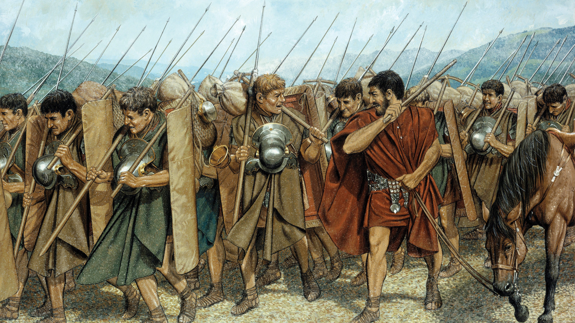
Much more than a simple weight, the sarcina was a symbol of discipline, resilience and autonomy of the most feared army of antiquity. Each soldier was trained to be almost an individual army on the move.
But what was inside the sarcina?
The Romans knew that victory began with logistics. So each legionary carried with him the essentials to camp, feed himself, shelter himself and survive for days, all on his shoulders.
Here’s what a Roman soldier carried:
●Dolabra (shovel/tile): used to dig trenches and build fortifications.
● Wooden poles (sweats): with these, they quickly erected defensive fences around the camps.
● Water ramp and clay or leather containers for carrying liquids.
● Portable mill: a stone mill to grind their own grain and produce their basic food ration.
● Iron frying pan, spoon and knife: for cooking and eating in the countryside.
● Rations: usually raw grain, dried meat, hard cheese, vinegar (mixed with water to purify) and even dried figs.
● Wool blanket or sheet (sagum): essential against the cold and rain.
● Spare tunic and personal items, such as coins, amulets or cards.
● Hygiene and sewing kit: because even an empire needs clean soldiers and tunics in good condition.
And all of this was tied together perfectly in a wooden frame, like a cross, fixed to a stick called a furca, which the soldier rested on his shoulder.
The most impressive thing is that these men walked for days, carrying everything, with the same rigidity and order with which they dominated the battlefields.
They were called, with a hint of sarcasm, “Marius’ mules”, in reference to General Gaius Marius, who reformed the Roman army and imposed that each soldier was responsible for his own equipment. A simple move, but one that transformed the Roman legion into a ruthless war machine.
The sarcina was not just a backpack. It was a symbol.
A reminder that Rome’s strength did not come only from swords, but from the ability of each man to stand, march and fight with everything he needed on his back.
Categories
One hell of a dog!
